Serving Yolo County, California
Motorola GTX Mobile Radio - Remote Head Modification
by Robert Schulz KC6UDSSeveral members of YARS recently began experimenting with the 33cm (902 MHz) band. The only readily available radio equipment for this band is converted commerial radio gear. One of the most commonly used radios is the Motorola GTX series, which is available in both a mobile and portable.
If you would like to learn a little more about the 33cm (902 MHz) band, here are a few links to get you started:
- Exploring 900 MHz by KB9MWR
- 900 MHz Technical Guide by the Guilford Radio Society
Motorola GTX specific information:
- The Motorola GTX Index Page compiled by Robert W. Meister WA1MIK, at the Repeater Builder's Technical Information Page
- Motorola GTX for 900 MHz Amateur / Ham Radio by Jason Buchanan N1SU
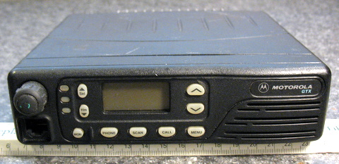
The GTX mobile radio is a small (as Motorola radios go) radio, slightly larger than the average modern dual-band amateur radio. As it was an entry-level model in the Motorola line-up, it was available only in a dash-mount version.
Having acquired a GTX mobile to use in the car, I was reminded of the annoying fact that most new vehicles are not at all radio-installation friendly. In particular, installing a dash-mount radio in a 2008 Toyota Camry is rather challenging, to say the least. This lead me to wonder if the GTX mobile could be modified for remote head operation, even though Motorola did not offer it as an option. I came up with a simple set of requirements for the project: The radio needed to work properly in a remote head configuration, there should be no special circuits or active electronics involved, it should be inexpensive, and the radio should be able to be restored to stock configuration if the modification was unsuccessful.
The short answer is: "Yes!" The GTX mobile can be modified for remote head operation. One important note - I did not carry this project through to final complete installation in my vehicle. About the time I was ready to do so, I acquired an MCS2000, a much more capable radio than the GTX, which has a standard remote head option, eliminating my need for a remote head version of the GTX. In addition, I was not able to read or program the GTX while it was in the remote head configuration. Reattaching the head directly to the radio restored programming ability. I did not spend any time attempting to troubleshoot this problem. All other radio features functioned normally while in the remote head configuration.
Obligatory disclaimers: 1) As with all projects of this sort, consider yourself warned that you do this at your own risk, it could cause damage to the radio, you if you aren't careful, and all sorts of other disclaimer-type warnings. 2) "Motorola" is a registered trademark of Motorola, Inc. 3) Known issues with this modification: Loss of ability to program the radio while in the remote head configuration.
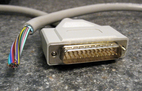
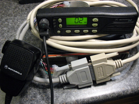
So, let us begin. Here is a picture of the GTX mobile radio:
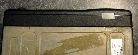
The first step is to remove the head of the radio. Turning the radio over, we can see two slots on the underside:
Inserting the tip of a flat bladed screwdriver into the slots and gently prying allows us to pop the head off. Note that the heavy red rubber gasket will provide some resistance while you remove the head. Here is what it looks like with the head removed:
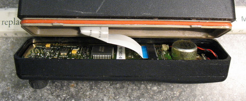
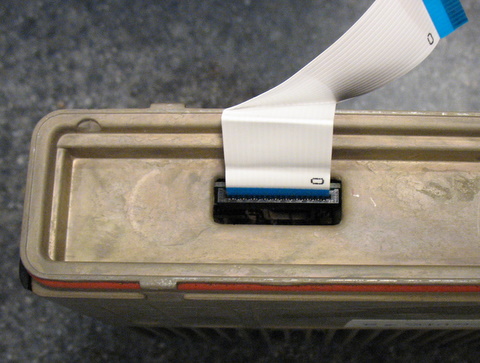
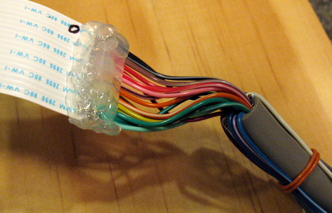
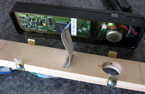
Looking closer, we can see that the only thing connecting the head to the body is a single ribbon cable (note the "0" mark on the cable):
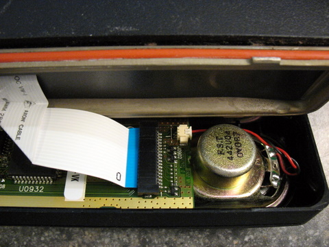
Detaching the ribbon cable from the head, and removing the foam pad from the front of the radio body, we can see the ribbon cable socket in the main unit. Note that the ribbon cable to socket connection is simply a friction fit - you remove the ribbon cable by gently pulling straight back from the socket:
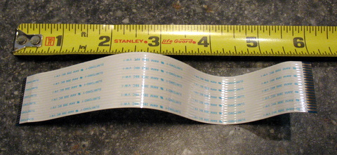
If the only thing connecting the two parts of the radio is a single ribbon cable, it seems like a simple solution would be to make that ribbon cable a good deal longer. Examining the ribbon cable reveals that there are 18 conductors in it. The first thought is "Can I just get a really long ribbon cable (say 10 or 15 feet long) to replace the stock one?" Doing some research reveals there are many different styles of ribbon cable, with different conductor styles and spacing (this cable has a connector spacing, or "pitch" of 1.25mm) and so on. Tracking down the manufacturer from the name on the cable reveals that while it would likely be possible to get a custom replacement, it would be cost prohibitive.
So, the next option would be to build my own cable extension. 18 conductors is a little bit of an odd number for standard multi-conductor cable. So the next question is, can I omit any of the signals in the ribbon cable to get to a readily available conductor count (such at 16 or 12)? To determine if that is possible, we need to know is what signals travel through the cable. A little research gives us the following table:
GTX Mobile - Main Unit to Control Head signal list
Main Unit Pin |
Signal |
Control Head Pin |
| 18 | ON_OFF_CTRL | 1 |
| 17 | FLT_A+ | 2 |
| 16 | MIC | 3 |
| 15 | BUS + | 4 |
| 14 | HANDSET AUDIO | 5 |
| 13 | ANALOG 3 | 6 |
| 12 | LED_CE | 7 |
| 11 | ANALOG 2 | 8 |
| 10 | ANALOG 1 | 9 |
| 9 | +5V | 10 |
| 8 | LCD_CE | 11 |
| 7 | GND | 12 |
| 6 | SPI_DATA_BUF | 13 |
| 5 | SPI_CLOCK_BUF | 14 |
| 4 | PTT | 15 |
| 3 | HOOK | 16 |
| 2 | SPKR - | 17 |
| 1 | SPKR + | 18 |
The first thought might be to combine speaker ground and power ground. Bad idea - all the GTX technical information out there says that you should never connect speaker ground to any other ground - doing so will destroy the audio amplifier. There are two signals on the list that might be candidates for omission from an extension cable: HOOK, which is related to the PL/CSQ select when the microphone is in a special grounded mic hanger, and HANDSET AUDIO, which is receive audio for when a telephone-style handset is used in the place of a regular microphone. In the end, after looking through the junk box and finding some old 25-pin shielded serial cables, I decided to use those to make the extension, which meant I could carry all the signals.
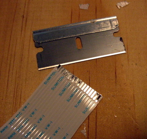
So, how to extend that little ribbon cable? I didn't want to damage the cable I had and render the radio unusable if the remote head project didn't work out. I remembered seeing similar style ribbon cables in a dead VCR I had been troubleshooting at work; pulling the machine from the scrap pile revealed a 19 conductor ribbon cable with the same 1.25mm pitch. The sacrificial cable had been found.
With a pair of scissors, I carefully cut away the unneeded 19th conductor. Note that the outer edges of this style of ribbon cable have extra width - trimming away a conductor from one side will result in a narrower edge that could allow one to mis-align the ribbon cable when inserting it into the connector. Pay careful attention to alignment when inserting the cable. Once I had trimmed away the extra conductor, I then cut the cable in half, and with a razor blade, carefully removed the insulation from one side of the cut end:
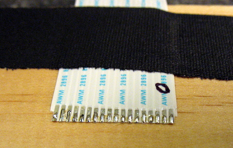
I then tinned the exposed conductors and marked the cable to help keep my wiring correct.
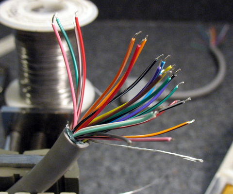
I cut a short serial cable in half to give me my connector pigtails for the radio head and body.
I stripped and tinned the cut ends of the serial cable, and determined the cable's pin-out/wire color code.
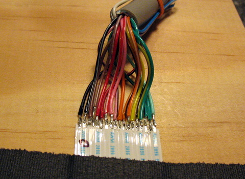
I then carefully soldered the serial cable wires to the ribbon cable:
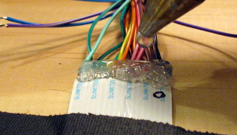
After testing for shorts between the different conductors, I covered everything with hot glue to prevent shorts and provide reinforcement to the delicate connections:
After a bit of careful work, I had two ribbon to serial cable adaptors built - one for the body (with a female DB25 connector) and one for the head (with a male DB25 connector). The female connector was used on the radio body side because there will be active power on that side whenever there is power applied to the radio body, even if the head is disconnected. At this point, I connected the two DB25 connectors together and double-checked that I had maintained the proper pin-out for the ribbon cable. Also, note the unused wires tied back:
I also had a long 25-pin serial cable in the junk box. However, I wasn't sure whether it was a null-modem or straight-through cable, so I had to test the cable to confirm (it was a straight-through cable, which is what I needed). Note that I've put unused DB25 solder connectors on the ends of the cables. The solder cups on the back of the connectors are a lot easier to hit with the meter probes than the pins and sockets on the connectors themselves.

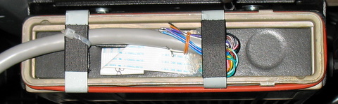
Attaching the pigtail to the radio body was fairly easy - the ribbon cable was inserted into the socket in the front, and the cable was held in place by some sheetmetal clips hooked over the snap tabs for the radio head:
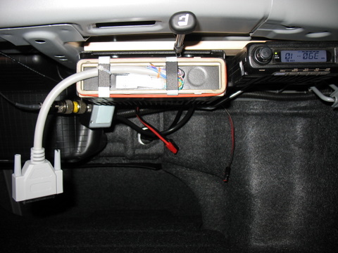
Here is what the radio body looked like mounted in the trunk (yes, the other radio is mounted upside down):
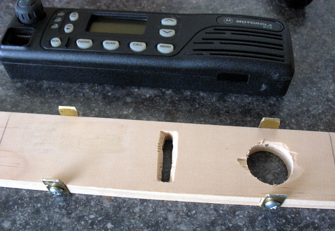
Connecting the pigtail to the radio head and making a mount for the radio head was a bit more challenging. While this part of the project was never completed, here's what I did do. First, note the notches on the inside of the radio head that the tabs on the radio body snap into. There are four of them:
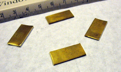
I carefully measured the notches, and cut some small bits of brass to make tabs:
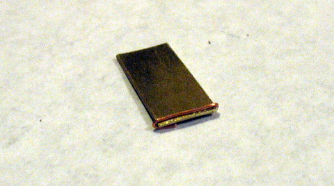
I then carefully wrapped a piece of small gauge copper wire around the very end of the tab:
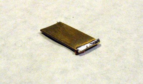
I then soldered the wire in place to create the ridge on the tab that would snap into the notch on the inside of the control head:
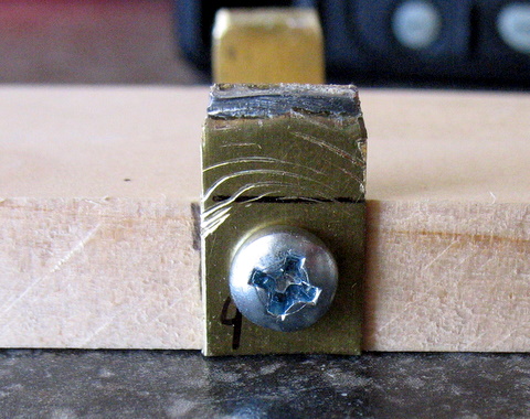
Finally, I drilled holes in the tabs and mounted them on a piece of board. Note how the edges of the tabs have been filed down to make the ridge end of the tab slightly narrower than the control head notch size.
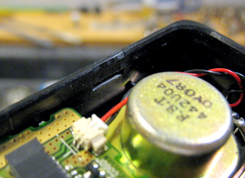
The mounting board needed two holes cut - one for the ribbon cable and one for the back of the control head speaker:
The pigtail was then attached to the board with a cable clamp and the ribbon cable was brought out the hole:
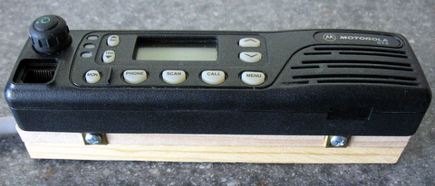
After trimming away excess wood and adding some protection for the remote cable, we have a functional, if somewhat unattractive, mount for the head:
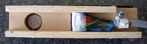
With a little more work, it would be possible to fashion a complete mounting bracket for the remote head. Here is a picture of the underside of the head mount:
Here is a picture of the complete remote head GTX radio (minus the mounting bracket for the head):
Concluding comments:
My main goal was to see if it was even possible to modify the GTX mobile for remote head operation. It most certainly is. All features of the radio, with the exception of programming, worked properly, and the modification was completed in such a way so that the radio could be returned to stock configuration.
I was not able to read or program the radio with the remote head modification installed. I did not spend any time trying to troubleshoot this, so I don't know if it was simply a matter of too much wire, or if there was a bad connection somewhere in the cable.
This is but one of several different ways of doing this project. Several options that I considered, but did not pursue, were: Obtaining a dead GTX to salvage another ribbon cable and the ribbon cable sockets, so I could build an extension without having to splice a ribbon cable, and then cutting up the dead radio body's frame to create a mount for the radio head; Omitting the two signals mentioned above to get the conductor count down to 16 so I could use two parallel ethernet cables, or if I could have gotten the conductor count down to 15 (feasible if one is using an external speaker), using a VGA cable for the extension. However, with using the 25-pin serial cable, I had 7 (8 if one counts the cable shield) extra conductors. Had I continued with this project, I would have used those extra conductors for something else, such as for the remote head of my Yaesu FT-8900, or for remote indications and control of my APRS tracker unit.
I finally abandoned this project when I acquired an MCS 2000 to replace the GTX. The MCS 2000 is a more versatile radio, and remote head capability is a standard feature. This project can certainly be taken as a "proof of concept" that the GTX is remote head capable.
by Robert Schulz KC6UDS, July 26, 2008